Here you can see the setup for optical preview of the sample. The preview was intended to be placed on a optical bench. The main objective was to make it quite compact and easy to use (no need to adjust anything between uses).
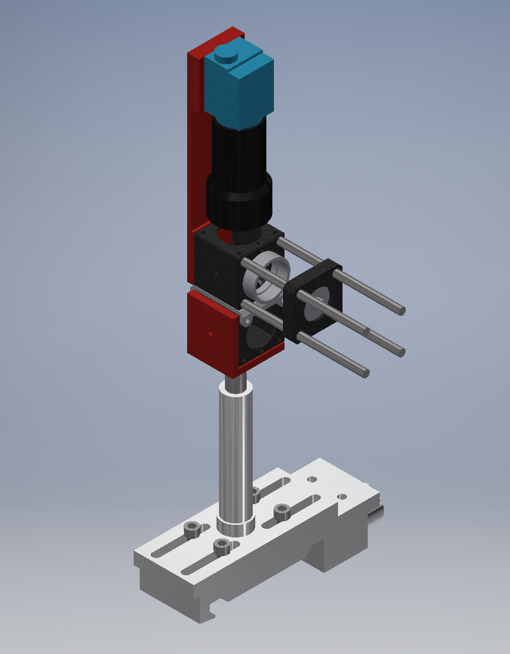
A view on a preview setup designed in 'Autodesk Inventor'.
The setup uses mostly thorlabs 30 mm cage system, but there are also a few elements that I had to order on our faculty's mechanical workshop (shown above in red). The setup comprises of:
- thorlabs cube mounted pelicle (CM1-BP108)
- thorlabs cube with polca-dot beamsplitter
- thorlabs cube connector (CM1-CC)
- 4 x thorlabs assembly rod (ER4-P4)
- a short lens with a mount
- thorlabs cage plate (CM02/M)
- thorlabs adapter plate for optical fiber (SM1FC)
- optical fiber connected to a white light source
- ccd camera with infinity adjusted objective
- custom made mount for the bottom cube (to turn it 90 degrees)
- custom made mount to connect the CCD camera to the upper cube
Below you can see the testing phase of the setup: no custom parts and a second pelicle instead of a polca dot. It is a proof of concept and works well. However the second pelicle reflects very little light and a polca dot is needed to shine more light on the samples surface (and therfore to better see the sample surface).

Testing the preview without the custom made elements.
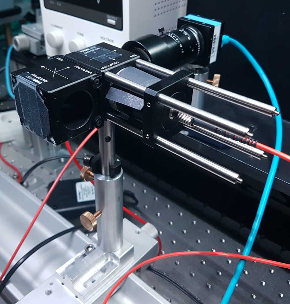
Another look at the test unit.
Why would you even want to use such a setup? Imagine that you are investigating small features on the sample, like a micropillar (SEM micrograph shown below) or a very small flake of some dichalcogenides. You would like to focus laser on such an object.
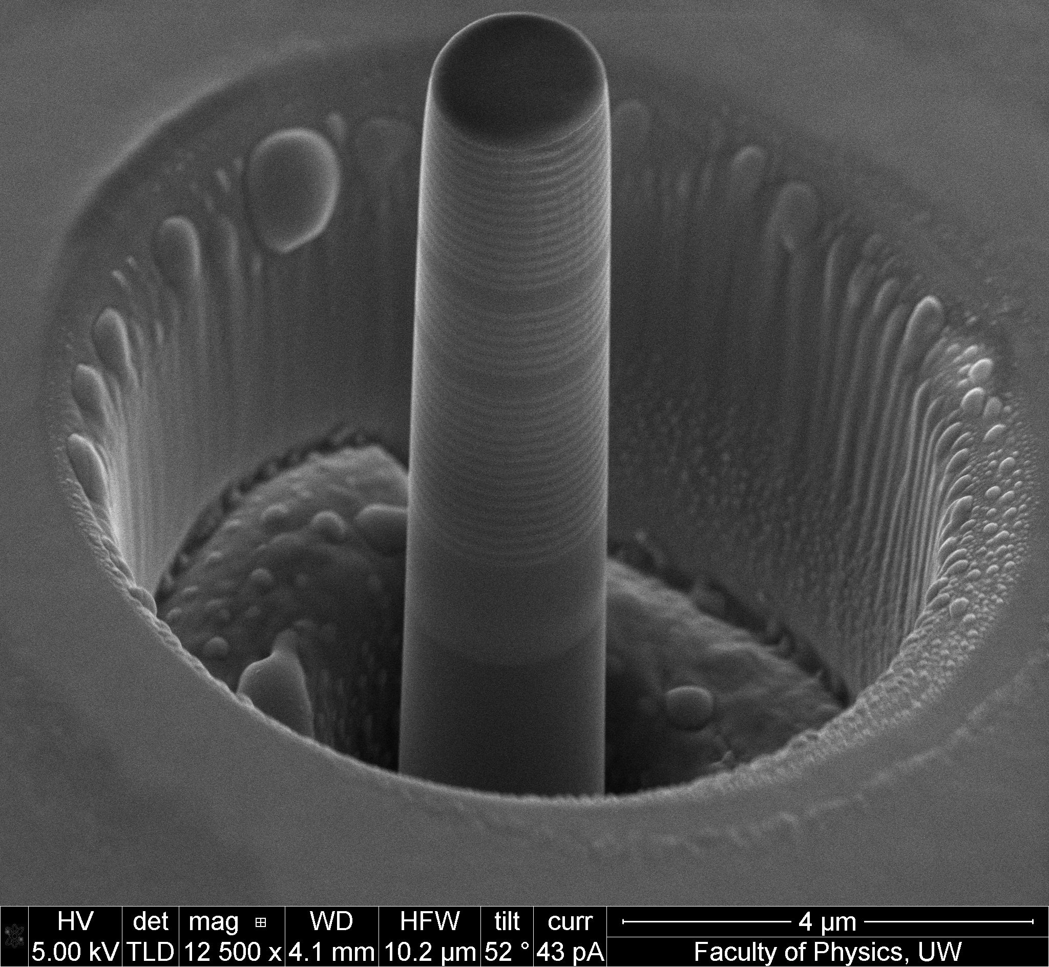
A scanning electron microscope picture of a 2 um micropillar on which we would like to focus our laser spot.
The problem is that it is very hard to find such features on the sample. Below is placed a SEM micrograph of the sample with micropillars). Without the preview setup it is virtually imposible to find the micropillars during measurements...
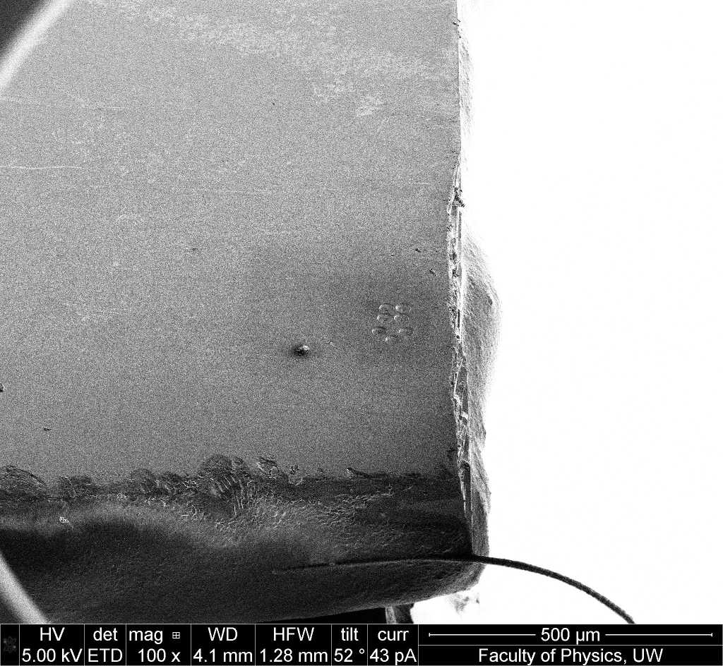
A micropillars array (in the middle) seen from far. Not so easy to find them on a large sample...
Finally, below you can see the image as seen by a ccd camera of the preview setup. Here you can see a 10-um micropillar with a green laser spot over it. As you can see, finding your micropillar is not that hard anymore.
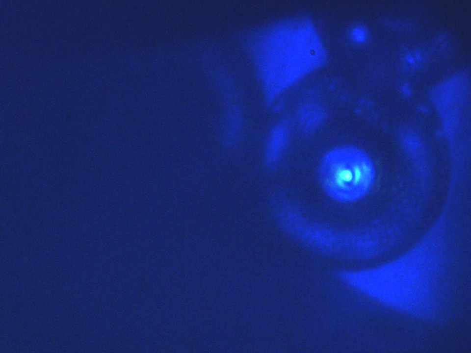
A laser spot on a 10-um diameter micropillar.